Sunday, September 13, 2009

Barcoola MKII triangle boards construction pictures


Hi All

Here are some pictures of the construction process of the Triangle boards.

1st picture, has the completed base scenery, with the points in place.

2nd picture, is the underside of the board with cut outs for the connector, the reverser, bus wires and tool clips which are used to attach the triangle board to one of the old barcoola boards.

3rd pciture shows the process used to make the roads, 600GSM card with tracings to establish the correct road size.

4th picture shows the road sections being cut out to fit, prior to being painted, and final installation.

Scott

Barcoola MKII new boards construction pictures part 3


Hi All

More pictures of the MKII boards.

The first picture shows the completed base scenery, The track has been installed, painted then ballasted.

The second picture shows competed mainline trackage at the Alice Springs and Perth ends of the layout, before being cut into the various board sections.

The Last picture, shows new boards 2 and 6 set up for transit. The wiring is completely protected as are the connectors.

Scott

Barcoola MKII new board construction pictures part 2


Hi All

Continuing the pictures of the new Barcoola MKII boards.

First Picture, is one of the foam boards, painted, and base scenery, waiting for track to be installed.

Second picture, The points were prewired and positioned using the tracing paper templates made from the original track diagrams applied directly to MDF base of each board. The centre lines were transposed to the foam base, prior to installation of the track base made from cork.

Third picture, the cork has been laid directly over the base joints, the cork was glued to the foam base using acrilyic sealant, two thicknesses of cork have been used for the mainlines, one for the yard or track was laid directly on the foam. Map pins were used to hold the cork in place while the sealant cured. The scenery was shaped smooth using a sander, as was the cork, to ensure the track height transitions were smooth. Finaly the scenery was painted Bristol Burnt Sennia.

Forth picture, shows the Tool box clips which are used to hold the boards together. The cork has been held in place using map pins.

Fifth picture, shows new boards 2 and 3 in the process of being painted. drains have been installed into the foam using a soldering iron.

More to follow.

Scott

Barcoola MKII new board construction pictures


Hi All

I have uploaded 5 pictures of the construction process.

The first picture shows the completed frame with 12mm ply ends and 3mm base. The centre line of the track is shown on the 3mm MDF. wiring connectors are upside down, and are shown as 140mm size MDF squares.

The second picture, shows the acrilyic sealant applied, ready for application of the foam base.

The third picture, shows the 50mm foam cut out ready for installation into the base. Cut outs have been made for wiring to pass through the boards, and access holes for attaching the wire droppers from the track to the bus wires.

The fourth picture, shows the base foam installed with the bus wiring also installed.

The fifth picture, shows the 30mm sandwich sections in place making the embankment for both mainlines, erosion ruts were made using a hot wire cutter, with the remaining scenery was completed using left over contruction site foam, shaped again using a hot wire cutter. sections were all glued together using acrilyic sealant.

More following.

Scott

Barcoola Old Boards rebuild


Hi All

These are pictures of the current state of the old scenery boards for Barcoola.
It as a little harder than first thought to "thin down" these boards, basicly the boards were kept together in their transit format. The legs and ancillary items were removed. Each transit end was removed one at a time and any screws were removed from the proposed location of the cut. The transit ends were then re installed and screws temporarly installed to hold the transit ends in place while the boards were cut down using peter's circular saw (thanks man).

The end result is shown in these pictures taken in my work shed.

Scott

Wednesday, September 9, 2009

Barcoola old scenery boards on a diet

Hi All
As of tonight four of the old scenery boards have gone on a diet and have been substantualy lighten. I thought that there was not much weight loss, until I picked up two un-modified boards and realised that the weight loss was more than I first thought. Although these boards are not as light as the foam boards they will be easier to move around and set up at exhibitions, which is the aim of this exercise.
Total thicknesses removed are 60mm, +60mm, +60mm and +80mm.
In this arrangement we should be able to all the scenery boards and ancilary bits in to the one trailer.
The modified boards are to be re-wired, for straight DCC operation. A Re build of the final yard board has also been considered, removing the "live" frog points with dead frog points, will limit the number of shorts.

Alice Springs
I am still fiddling with the arrangment of Bow River and Barcoola. Hevatree gap, I needed more width currently I wanted to add the rock work, Stuart Hwy, Todd River and more rock work. This would add 5 and a Half foot wide section. I was also not happy with the closeness of the hwy overpass. So I have removed all but one. The model of 555km Quarry is gone but it has been converted to single run off track with a 36 inch minumum radi
Barcoola as been modified to add more storage sidings, but these are dead ended, to make the track arrangment more like Tarcoola. These sidings are have the capacity for one entire train.

Anyway I will put up a scan of the new diagram when the scanner stops sptiting the dummy at me.
I still have to figure out the final grades, and this will depend on the final placement of Barcoola.

Glen has started on cattle wagons for barcoola MKII, and these will be right at home going to Bow River, thanks man.

Scott

Friday, September 4, 2009

Barcoola and Alice Springs no grade


Hi Guys

I am happy with the arrangement of Alice Springs yard and industrial area. The industrial area has been slightly modified, after a bit of google earthing as follows:
The Mobil facility was extended, both sidings and fuel station.
Kleenheat Gas has been added including the siding.
Adelaide Brighton Cement was extended.
All other sidings have been deleted.
Ghan Road has been continued right though to Smith street as per prototype.

Barcoola has a double reverse curve added.
555Km Quarry siding has been reversed and the siding sneeks back into Bow River yard,but not into controlled territory.

Hevatree Gap has been widened to include the Todd River.
Plenty of room has been provided for aisle way up and down Alice Springs yard, as in this version there would be plenty of traffic to and from Bow River.

The down side is we loose the triangle at Bow River, not happy jan!!.
Plus is a possible location for a triangle turning power at Barcoola.

Anyway, Planning is now in the polishing stage.

Phase I Alice Springs yard can be put into production, regardless of the final configuation. Phase I will be Alice Springs with a temp fiddle yard. So Board construction can commence.

thanks

Scott

Tuesday, September 1, 2009

Barcoola and Alice Springs


Hi All

For all of my friends that have had to put up with me sticking enless layout diagrams under their nose for coment please see the two images are plans of a future Alice Springs layout which will include Barcoola in name only, Barcoola is basicly an open staging yard. The First version has no duck unders and long distances between locations and the section around the edge of the room are double stacked, the lower level is Barcoola - northgate(southern open staging) and the upper level is Berrimah yard (northern opern staging). This version was finaly rejected due to a couple of factors.
1 the radi at Bow River was just too tight.
2 too much hidden trackage, the southern line would have to be unseen from the south switch of Bow River to just out of Barcoola.
3 Too many grades, although they were not steep, they would just be a complete pain to construct, thus it would take longer to construct.
4. Alice Springs yard would be too squashed and curvy, all thoes curved points would create problems shunting.
5 not enough people space, and the plan was not linear, meaning when you are at one part of the layout you would then have to walk around the entire layout just to keep track, this would increase the aisle traffic dramiticly.

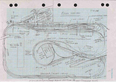
Late last night I came up with the final version, one I would call "proof of concept".
this version is not walk in, but is linear.
Alice Springs yard is easier to shunt, it is longer and more managable, I have positioned all the points out on the floor and checked the track lengths using Micro Engineering #6 points.
Alice Springs industrial area is better represented as a "mini layout" and the roads are the correct orientation.
All sidings are 22ft clear standing distance.
Plenty of space for operators and "train control" (the Bar)
I have added the 555km Quarry as this will keep train control busy with addtional train orders from Barcoola to 555km.

Anyway I hope this makes some sence.

thanks

Scott